(This page was created by D.G. Sarantites and was last updated on Sunday, May 9, 2004 3:40 PM .)
You are visitor No.
since September 11, 1999.
The Neutron Shell was designed especially for use in conjunction with the Gammasphere and often with the Microball for the purpose of selecting one and two neutron evaporation channels in very neutron deficient systems for far from stability gamma-ray spectroscopy. The Neutron Shell consists of up to 30 tapered hexagonal detectors that replace the 30 Ge-BGO modules of the 6 most forward rings of Gammasphere.
The design of the geometry of the Neutron Shell for Gammasphere is
dictated by the constaints imposed by the geometry of Gammasphere. A
series of Monte Carlo simulations were performed by the LBL and the
University of Pennsylvania groups using the code GEANT.
It was concluded that the optimal cost effective solution is to
approximate the BGO elements with a uniform regular tapered hexagonal
geometry that packs on the average as well as possible.
A schematic representation of the shell is seen here. (a) Shows a
side view of the Shell and (b) the front view as the beam or neutrons
see it. If you are using Netscape, right click and choose "View Image"
to see the picture with more resolution.
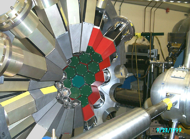
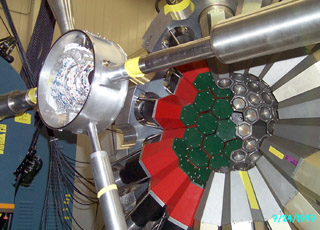
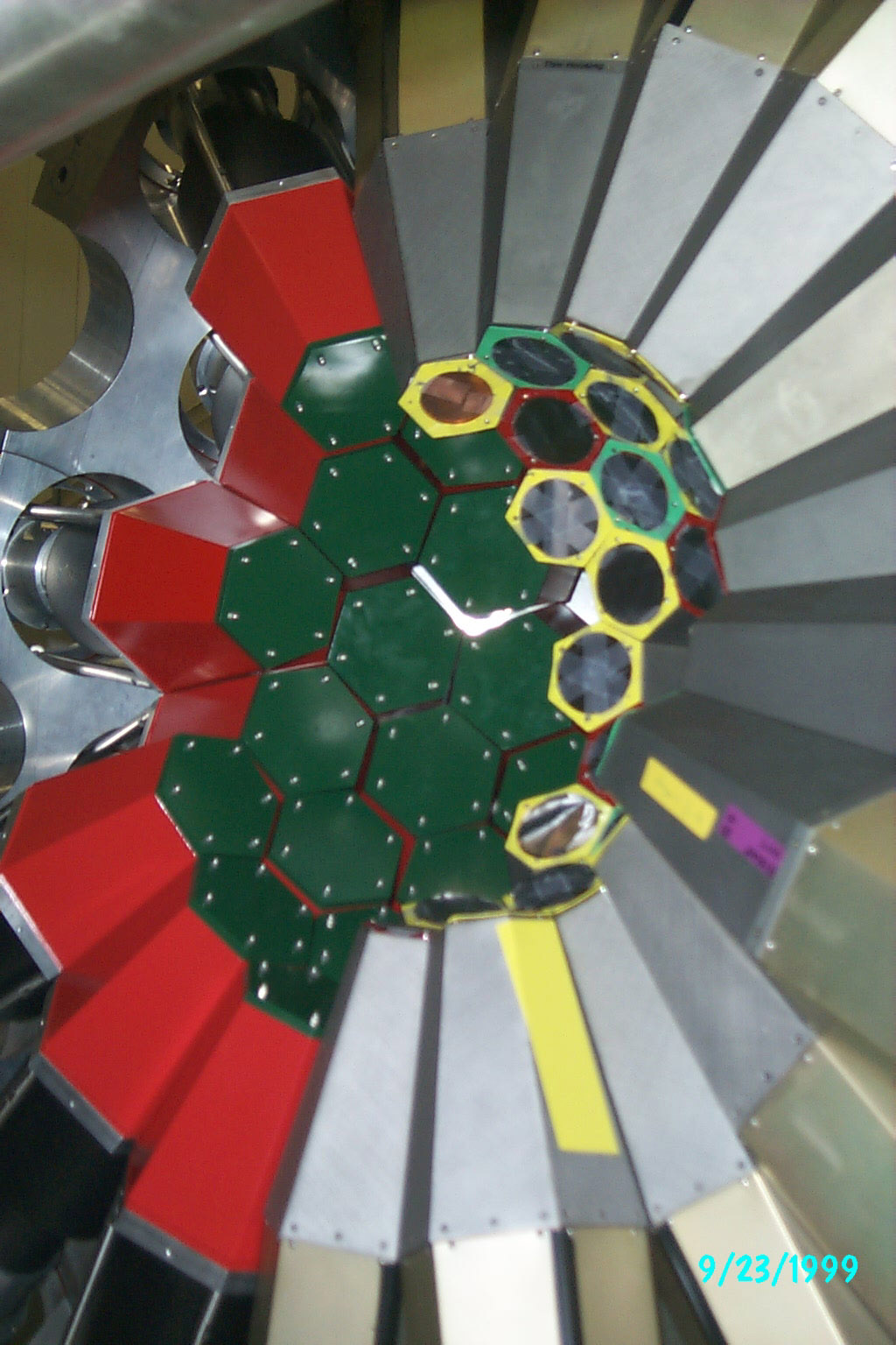
A photograph of the left hemisphere of the Neutron Shell is seen
here. The 8 mm Pb absorbers are seen painted green. The 1.2 mm Al
hexagonal containers are painted red. The expansion bellows have not
been installed at this time.
A high
resolution view (1024x1536) of the Shell as it being installed in
Gammasphere is available.
Here is the first working detector ! If you are using Netscape, right click and choose "View Image" to see the picture with more resolution.
The design of the neutron detectors was done by D. Sarantites. The
construction plan was produced in close consultation with Jim Linders
of the Washington University Chemistry department machine shop.
First, the detector housing was made from tapered spun funnels made of
1.2 mm thick aluminum.
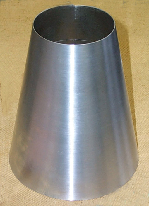
A close-up photograph of a funnel is seen here. It was first spun,
but the spinning process did not produced sufficiently uniform
thicknesses. Then the funnels were machined to uniform thickness, and
cut to the appropriate length.
A close-up photograph of a funnel being pressed into a hexagonal can
is seen here. A pressure of 2,000 atm was applied to bring the can into
the desired shape.
A close-up photograph of a finished hexagonal can is seen here.
Finally, the hexagonal can was cut to the exact length for welding to
the supporting flange and the end plate. If you are using Netscape,
right click and choose "View Image" to see the picture with more
resolution.
The hexagonal cans were cut to the exact designed length. Then the bottom of the can was welded on. It has the appropriate shape and it is sufficiently thick to allow tapped threads to be made that will support the Pb absorbers with 6 screws.
The top hexagonal flanges are the most important part of the detector housing. They have appropriate grooves for the quartz windows to be held for sealing. Also the provide the tight fit for the µ-metal shields. They also have the threads for the three support rods that connect the detectors to the BGO-like flanges that in turn couple to the Gammsphere shell. Forteen of the cans are seen here. They have been painted on the inside with the TiO2 based epoxy-type reflector. If you are using Netscape, right click and choose "View Image" to see the picture with more resolution.
Enjoy!
(Under construction)
The Neutron Shell for Gammasphere provides a multitude of methods for neutron-gamma discrimination.
 A preliminary set of PID maps is shown here.
The panels are self explanatory. The source is 252Cf with
the start from a CsF fast scintillator. For in beam samples of maps
please wait after the New Millennium starts.
A preliminary set of PID maps is shown here.
The panels are self explanatory. The source is 252Cf with
the start from a CsF fast scintillator. For in beam samples of maps
please wait after the New Millennium starts. In the offline analysis several tricks can be used to simplify and
enhance the ease of neutron and gamma separation. If you are a user of
this array you may learn about these tricks by contacting DGS at:
dgs@wuchem.wustl.edu
Back to the Top.
 The Neutron shell and the Microball
in Gammasphere are seen here. The neutron detectors are colored red
while their 8 mm Pb absorbers were painted green. The Microball
chamber is open on both sides. Only half of the Neutron Shell is
visible in this hemisphere with 16 detectors in place. The beam
enters from the right. The FMA quadrupole magnet is seen on the left in
blue. A high
resolution view (1395x1004, 356 kB jpg file) of this picture is
available.
The Neutron shell and the Microball
in Gammasphere are seen here. The neutron detectors are colored red
while their 8 mm Pb absorbers were painted green. The Microball
chamber is open on both sides. Only half of the Neutron Shell is
visible in this hemisphere with 16 detectors in place. The beam
enters from the right. The FMA quadrupole magnet is seen on the left in
blue. A high
resolution view (1395x1004, 356 kB jpg file) of this picture is
available. The best operation of the Neutron Shell relies on the use of the
excellent timing resolution of the ATLAS accelerator. Typically 1.0 ns
FWHM is easily archived after minimal effort with re bunching. The
start of the timing is made by the RF enabled by the Gammasphere
Pre-trigger timing signal.
The setup provides for a convenient and easy way to align the times
from the zero-crossing discriminators. Since the latter timing can be
made essentially pulse height independent it is possible to apply a
hardware veto for the gamma flash within the time required to provide
the external bit for the neutron array. The result is that for mixed
triggers (n-g-g) + (g-g-g-g) for example, the computer dead time is
reduced substantially. This enriches the data set in the desired
neutron coincidences by 30-40%. The alignment of the times is done
with programmable ECL delays.

This is a schematic diagram of the electronics for the Neutron-Shell setup of the 9 experiments done at ATLAS with the Gammasphere, Microball and the Neutron Shell. The diagram is almost self explanatory. Sorry, but all the Module models are not given. If you are using Netscape, right click and choose "View Image" to see the picture with full resolution.
A
pdf file of the electronics setup can be found here.
For more details wait for a while or contact DGS: dgs@wuchem.wustl.edu
The Neutron Shell had its maiden experiment on September 27, 1999. It was used in conjunction with the Microball in an experiment to search for new structures below the 60Zn. The experiment worked very well and data were obtained. Also the performance and tuning of the array was done. The hardware gamma veto was implemented and worked satisfactorily.
The first group of experiments performed with the Neutron Shell and the Microball was:
This marks the first and last Microball + Neutron shell experiments with Gammasphere at ATLAS.
The Neutron detector gain matching was done approximately with the 2615 keV gamma from a 228Th source. The edge of that gamma was placed at approximately channel 1900 in the high gain energy spectra. It corresponds to about 6 MeV in neutron energy.
For the calibration files of the Microball from MB-55 see the Microball home page.
The setup had 78 Ge detectors in Gammasphere, 30 Neutron detectors and 94 out of 95 working detectors in the Microball. In experiment MB-56 the detector 14 fixed "itself". From then on all 95 out 95 detectors in the Microball work.
The configuration file for the Neutron Shell contains angles and positions of the neutron detectors in Gammasphere. Configuration file for the Neutron Shell.
The time stability of the Neutron Detector timing relative to the RF was monitored for each experiment. It was found to be very good. In NS-3 and NS-4 the timing of detector 11 was jumping with time. Later on it was stabilized. All detectors resolve the gamma rays from the neutrons by 3 methods and 4 ways.
( Back to the Microball Page).
For comments and corrections send mail to: dgs@wuchem.wustl.edu